Programming STM32 "blue pill" with HAL and Eclipse
Unfortunately programming this board is not as easy as programming an Arduino board. There is a project named STM32duino aimed at simplifying things which makes use of Arduino IDE and similar programming language. But, STM32 is a complex CPU with more functions than Arduino language offers. You can program it using Eclipse IDE and a set of libraries offered by ST. These libraries are LL (low level), StdPeriph (standard peripheral library) and HAL (hardware abstraction library). HAL uses high level API which simplify developing an application. This post will show you how to configure the development environment and write the first program with HAL that will blink an LED.
An easier alternative to Eclipse and HAL is PlatformIO and Mbed. Check it out.
CH341A SPI Programming (Windows API)
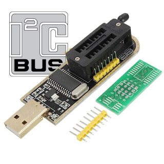
CH341A is used by some cheap memory programmers. The IC is somehow limited in this configuration, because the programmer makes use only of the SPI and I2C interface. A popular device is the so-called "CH341A MiniProgrammer" that you can buy for 2 to 5 USD. And this is probably the cheapest device using CH341A.
If you got a "MiniProgrammer", you may want to use for more than memory chips programming. The device can actually be used as USB to SPI converter (not only SPI, but this article will focus only on SPI function). Let's see how to use the included library and header to communicate with SPI peripherals.
CD4017 and NE555 Light Chaser Circuit
NE555 is configured as an astable multivibrator. Oscillation frequency is rather low for this application. It is determined by R1, R2+RV1 and C2. With the values used for this circuit, it can be adjusted between 10 and 65 Hz. The duty cycle is close to 50%. If you want to calculate it yourself, use this tool.
Drive stepper motors with Arduino (code)
A stepper motor is a brushless electric motor that rotates in small equal steps, as opposed to the continuous rotation of regular motors. It has the ability to rotate a predefined number of steps, being made of multiple coils that are energized in regular sequences by trains of digital pulses. Unipolar motors use two coils, each of them having a center tap. The center taps from both coils connect to a power line and the remaining four coil terminals are powered sequentially (they have at least 5 wires). On the other hand, bipolar stepper motors have two coils that are powered one after another then voltage polarity is reversed and coils are powered again (this type of motors have only 4 wires).
A simple transistor driver and connections (only for unipolar steppers) and driving methods were discussed in the previous post: Driver and Arduino code for unipolar stepper motors. Some basic Arduino functions were provided there. But those functions are too basic for most usage scenarios. The motor can be driven only in with multiples of 4 or 8 steps and you can't change rotation direction. In this post, I will explain further the driving methods and I will generate driving pulses programmatically, with the ability to move one step at a time and change the rotation direction.

Set up STM32 "blue pill" for Arduino IDE
The "blue pill" is a STM32F103 based development board. Although it is less popular, the board is cheaper than the Arduino Nano. More than that, STM32F103 is a device with Cortex-M3 ARM CPU that runs at 72 MHz, 20 kB of RAM and 64 or 128 kB of flash memory. The microcontroller (MCU) has USB port, two serial ports, 16 bit PWM pins and 12 bit ADC pins. It runs at 3.3V, but some of its pins are 5V tolerant.
Programming the board can be simplified using the popular Arduino IDE. But before this, an Arduino-like bootloader must be flashed to the board. This can be done via serial port or using the debug interface of the MCU with ST-Link tool. There are also some small hardware issues with Chinese boards that need to be fixed. This post will show a straightforward guide for setting up this board to work with Arduino IDE on Linux and Windows. The instructions below are based on STM32duino wiki [down?] documentation.
Driver and Arduino code for unipolar stepper motors
A stepper motor is a brushless electric motor that rotates in small equal steps, as opposed to the continuous rotation of regular motors. It has the ability to rotate a predefined number of steps, which makes it useful for precision mechanical devices. To do this, it uses multiple coils that are energized in regular sequences by trains of digital pulses. The speed of these pulses determines the speed of the motor. The pulse sequence determines the rotation direction. Nowadays, you can find integrated drivers for all types of stepper motors. In this post you will learn to make your own driver and use the motor with a development board.
There are two main types of stepper motors. There are bipolar motors which contain two coils (4 wires). To drive this kind of motors, coils are energized one after another, then polarity is changed and the coils are energized again. Two H-bridge circuits are required in this case. Unipolar motors use two coils, each of them having a center tap. The center taps from both coils connect to a power line and the remaining four coil terminals are powered sequentially (5 wires). Unipolar mode simplifies a bit the driving circuit. Some manufacturers offer steppers that can be used either as unipolar or as bipolar. This kind of motors have the center taps not connected together (6 or 8 wires motor) and if the center taps are not used, the motor can be wired as bipolar.

Unipolar stepper driver built on perfboard
Receive DRM Radio on Linux with Gqrx and Dream
 |
| Dream decoding a DRM broadcast |
Script to compile and install PulseView on Ubuntu
You will find in this post a script based on building instructions from official sigrok/PulseView wiki that automatically downloads, builds and installs all required dependencies and PulseView itself. The script has been written and tested on Ubuntu 17.10 but it should work on other apt based distros.
Light or dark activated switch using Arduino
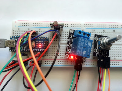
Using a microcontroller we can design a smarter device. One that does not activate the relay at every instant change of light (flash). The same device can turn from a dark activated relay into a light activated relay at a push of a button.
The following project uses an ATmega328 board with some modules which are part of a popular Arduino sensor kit. Don't worry if you don't have that modules. They are simple circuits for which I provided schematic.
Homemade PCB with toner transfer method
The toner transfer method is a cheap and easy way to make your own printed circuit boards (PCBs) at home. A laser printer is used to print the design on paper. Not all paper types are suitable for this kind of usage. The paper is placed with the printed side over the copper side of the circuit board and then the whole thing is heated. Most people use with good results a common iron, but if you have a laminator, use it instead of the iron. When heated, toner melts and sticks to the surfaces. The idea is to make it stick to the copper layer. After heating, the board is submerged in water and the paper should be easily peeled off from the copper side. A good transfer means no toner remains on the paper. Once this is done, the board can be etched using whatever method you want (ferric chloride for example).
This method is widespread among hobbyists because is cheap and easy. However, for some, the results are unsatisfactory and variable. I will share some of my experiences with this method.

Homemade PCB with silkscreen
Virtual Audio Cable in Linux Ubuntu
You probably need to do audio piping to record an audio output or to use SDR tools which only support audio input. You don't have to use a real cable to wire the sound card output into line in. The software approach is better. There is more than one way to do this in Linux. We'll look into Pulseaudio and ALSA, the sound servers used by Ubuntu. Depending on what application you use, you may need to configure the virtual connection on one or the other server.
PonyProg release 3.0 comes with modern UI
If you still have an older computer with a motherboard serial port, you may take into consideration building the serial adapter used by PonyProg, because it is easy to build and probably the cheapest programmer possible. The schematic of the interface can be found at the author's page (SI-Prog by Claudio Lanconelli).
Currently, PonyProg only support SI-Prog or other serial based programmers and some parallel port programmers. With serial port, it communicates by bit-banging various protocols to the signaling lines contained in the RS232 interface (RTS, CTR and DTR). It would be nice if a future version would support the modern USB based programmers (like the CH341A MiniProgrammer) which lack a good software.
 |
| PonyProg 3.0 main window after reading an I2C EEPROM |
CH341A I2C Programming (Windows API)
CH341A is used by some cheap memory programmers. The IC is somehow limited in this configuration, because the programmer makes use only of the SPI and I2C interface. A popular device is the so-called "CH341A MiniProgrammer" that you can buy for 2 to 5 USD. And this is probably the cheapest device using CH341A.
If you got a "MiniProgrammer", you may want to use for more than memory chips programming. The device can actually be used as USB to I2C converter (not only I2C, but this article will focus only on I2C function). Let's see how to use the included library and header to communicate with I2C devices.
FM Radio Player for RTL2832U sticks
The problem is that these applications have full featured SDR abilities, with spectrum analysis and waterfall display. This makes them not at all lightweight. I've been looking quite hard for a simple FM radio player for my RTL-SDR dongle.
Some of the RTL2832U dongles come with FM capable player on the CD. Unfortunately not all. After some searching I was able to find a simple tool that demodulates FM stereo signal and displays RDS data. The application was most probably a test tool designed by Realtek to illustrate features of RTL2832U.
CH341A Mini Programmer Schematic and Drivers
CH341A is an USB interface chip that can emulate UART communication, standard parallel port, memory parallel port and synchronous serial (I2C, SPI). The chip is manufactured by Chinese company Jiangsu QinHeng Ltd. CH341A is used by some cheap memory programmers. The IC is somehow limited in this configuration, because the programmer makes use only of the SPI and I2C interface and leaves a lot of pins unconnected. A popular device is the black CH341A MiniProgrammer that you can buy for 2 to 5 USD.
The problem with these devices is that you get them without any documentation or software. Drivers are available from manufacturer's website (but the site is written in Chinese). Also, some source codes are available from manufacturer. There are open source applications that support this programmer. But, first of all, let's have a look at the hardware.
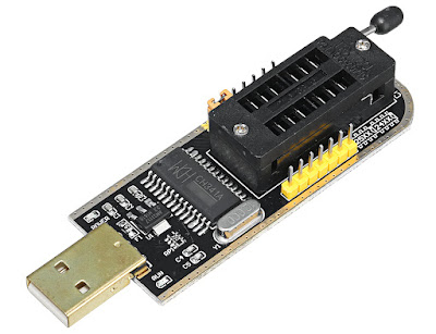
Photo of the black CH341A Mini Programmer
Heatsink for RTL-SDR dongle
Marko Cebokli (S57UUU) used a thermal camera to measure the temperature of the dongle. He measured up to 85°C at the tuner chip (R820T). His images prove also that the dongle PCB doesn't do a good job at dissipating heat.
Although I'm using a R820T2 dongle (which is said to heat less than the predecessor R820T), I was surprised to see that after only 10-15 minutes the dongle was hot. Opening it up, I discovered that all ICs were hot (the tuner R820T2, the RTL2832U, the 1117 regulator, even the EEPROM was heated inside the closed case of the dongle).
A 15-Segment VFD controlled by HT16515
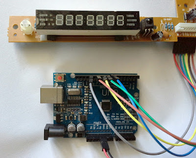
FV865ND is a VFD panel manufactured by Futaba Corporation. It is designed to be used in DVD players or set-top-boxes. It can show 8 characters and it has a lot of symbols (icons). I found it in a DVB-S2 receiver (Comag SL100HD) where it was used at the front panel with HT16515 controller IC. Fortunately, the front panel of this receiver contains everything needed to power the VFD (the power is supplied via 5 V line and it is converted to filament and VFD voltage by a small transformer located on the back side of the PCB).
I couldn't find any software for HT16515 but its datasheet is available. The IC is 3.3V and 5V compatible and the nice thing is that the panel connector has different pins for IC supply and VFD transformer. The IC supports key scan too and the front panel makes use of only 7 keys (maximum 32). Data is sent/received via 4 lines serial interface, SPI like.

Comag SL100HD front panel with VFD
SC75823 13-Segment LCD Display
The controller only supports writing data to it. There is no key input support like other front panel ICs that can control a display and read pressed keys. The panel I'm using had each key connected in series with a different resistor and the main processor read pressed key by analog read value. Since some keys didn't work anymore, I cut the PCB and removed extra parts, keeping only the LCD panel, its backlight and the controller.
The communication protocol is probably Sanyo CCB (computer control bus), somewhat similar to SPI (it uses clock, data and chip enable signals). The controller has a pin INH that when LOW turns off the display. The library supports turning display off via this pin if connected or using software command.
A different TM1628 7-segment display
The only Arduino compatible library I was able to find for TM1628 is developed by Vasyl Yudin and is available on GitHub. But, I couldn't get any readable output on display. That happened because my front panel had a different segment assignment to the controller than what I found on YouTube (the display with disc icon on it).
My front panel came from TeleSystem TS5.9RX DVD Recorder and it has 7 digits and some other indicator LEDs. The PCB also contains 5 keys - but I can expand it by adding more buttons. Below is a sketch example for this front panel. It is 5V compatible so it can be connected directly to 5V levels development boards like Arduino and compatible.
Using Magix USB-Videowandler 2 on Linux
Videowandler 2 is based on eMPIA 2861 USB chip. Video conversion is done by SAA7113 and audio conversion by EMP202. The IDs of the device are 1B80:E349. When opening the case, you may find printed on the board UB317 Ver:A or UB315 Ver:C. The latter my be identical to Kworld UB315 but I’m not sure.
 |
| Magix USB-Videowandler 2 board. Photo by Christian Enders. |
Turn RTL-SDR dongle into RTL2832U breakout board
The most popular RLT2832U dongles are the ones with E4000 and R820 tuners. This is due to the high frequency range these tuners have. Elonics E4000 covers 52 to 2200 MHz with a gap at about 1100 MHz and Rafael Micro R820T covers 24 to 1766 MHz.
But there are also RTL2832U based dongles with other tuners. One example is FCI FC2580 tuner (found in Trust 16738 dongle) which is capable of receiving 146 - 308 MHz and 438 - 924 MHz, limiting its use to DVB-T only! It can't even receive FM radio 88 – 108 MHz.
If you’re having such a dongle don’t throw it away. There are situations when you don’t need a tuner at all (the direct sampling mode of RTL SDR that allows direct reception of signals on frequencies lower than 28 MHz). There is also the possibility of changing the existent tuner with, for example, a satellite receiver tuner that will receive 950 to 2150 MHz.
So, I wanted a universal RTL2832U breakout board that I could easily connect to with different tuners. This is how the USB dongle board looked like.

RTL2832U dongle
Add and configure WAN port on OpenWrt
OpenWrt is a Linux based, embedded operating system for networking devices. Besides being open source, it is highly configurable and versatile. This post will show how to configure one of the LAN ports as WAN input (for xDSL routers, which have the WAN internally connected to the modem). There are no opensource drivers for ADSL op OpenWrt and this feature is therefore unavailable. It doesn't matter anyway, since DSL limited in bandwidth and is losing its popularity.
Many DSL routers are in fact more powerful platforms, with improved hardware, than ordinary routers. If you want to connect the router to wired LAN internet this is what you should do. I've done this on a router with a development snapshot installed (the difference is that development versions do not come with web interface preinstalled). If you have a regular release, you can skip LuCI installation, as you already have access to the web interface of the router.
Install OpenWrt on P.RG AV4202N router
Currently, although the BCM63xx platform is supported by OpenWrt, there are no releases for this device. Neither LEDE Project has released a stable build for this device, but they are offering a development snapshot [3]. The problem with LEDE snapshots is that they don't work out of the box without additional software packages (you don’t get any web interface).
But, LEDE can’t be installed on the device due to the locked bootloader. This article will show you how to use JTAG to install a different bootloader that can be used to flash OpenWRT/LEDE firmware. Part 2 details LEDE configuration and internet connection.
Generate good looking PCB artwork from KiCAD
KiCAD is probably the most complete opensource EDA suite. It comes with a schematic editor, a PCB designer and a 3D viewer. PCB designs can be exported to multiple formats or printed directly from the software. Although the plotting (printing) options are quite advanced, there aren't options for overlaying different layers with different colors.
This tutorial will show you how to create PCB artwork that looks good on display or print and that is intended only as a guide to the reader, not as a source for manufacturing PCB. The result will be a greenish PCB (or any color you want) with silkscreen on top of it. This is probably something you already seen in electronics publications.
There are many ways of doing this. All you need to start are the PDF files plotted by KiCAD and some image editing software (I prefer opensource tools: GIMP or some ImageMagick scripting).
How to compile librtlsdr on Windows
Librtlsdr is the backend used by most SDR applications compatible with the well-known RTL2832U demodulator. Using librtlsdr, you can get raw I/Q samples from RTL2832U chip, thus turning a cheap TV stick into a software defined radio (SDR).
Librtlsdr source code can be found on GitHub. It compiles easily on Linux hosts using instructions from Osmocom project. Compiling librtsdr on Windows is not that easy, mostly because the only two required libraries (libusb and pthreads) cannot be located using the same methods as on Linux (pkgconfig).

Make a buffered JTAG adapter (Wiggler)
JTAG is an in-circuit programming and debugging interface. It specifies the use of a dedicated debug port implementing a serial communications interface for low-overhead access without requiring direct external access to the system address and data buses. The interface connects to an on-chip test access port (TAP) that implements a stateful protocol to access a set of test registers that present chip logic levels and device capabilities of various parts.
JTAG interface is supported by many devices as a convenient way of rewriting firmware (specially boot loaders) when other methods fail. Using JTAG, the ROM memory can be directly written without desoldering it from PCB to program it using a specific programmer.
In most cases, you will need JTAG access to a device with a no longer working bootloader. Otherwise, if the bootloader runs, there should be easier ways of debricking the deice. Most of the times, a device with corrupt bootloader will not display any signs of working (i.e. no LEDs turned on in case of routers, no display on front panel of set-top-boxes). Nor any ports of the device will work (i.e. no serial port response, no network detected).
QSS syntax highlight in Qt Creator
Qt Creator is the IDE (integrated development environment) used by Qt SDK. It is a powerful piece of software that runs on Linux, Windows and macOS. Qt SDK is able to style built applications using QSS styles, something similar to CSS standard.
Qt Creator supports not only C/C++ syntax highlighting, but basically any language through Kate Editor Syntax Highlighting files. These are XML files that define lists of specific keywords. In this way, the Text Editor of Qt Creator is able to style these keywords using a color scheme.
Qt Creator doesn't have a default QSS syntax highlight configuration file. And neither Kate. But there are two ways to add QSS syntax highlighting to Qt Creator.


